DSC Impassa Installation Guide: A Comprehensive Plan (Updated 04/15/2026)
Today’s date is 04/15/2026 09:37:39. This manual assists with your new DSC Impassa system‚ offering a detailed walkthrough for successful setup and operation.
Welcome to the world of secure home automation with the DSC Impassa system! This cutting-edge security platform provides robust protection and convenient control‚ designed for modern lifestyles. The Impassa system isn’t just about deterring intruders; it’s about peace of mind‚ knowing your property and loved ones are safeguarded.
This guide will walk you through every step of the installation process‚ from initial planning and component setup to system testing and troubleshooting. Whether you’re a seasoned security professional or a first-time installer‚ this manual provides clear‚ concise instructions to ensure a smooth and successful experience.
The Impassa system boasts a user-friendly interface‚ wireless capabilities‚ and expandable features‚ allowing you to customize your security setup to meet your specific needs. Prepare to unlock a new level of security and convenience with the DSC Impassa!
Package Contents & System Overview
Your DSC Impassa package should include the following key components: one (1) Impassa Control Panel‚ one (1) Keypad (model may vary)‚ one (1) Power Supply with battery backup‚ and various wireless sensors (door/window contacts‚ motion detectors – quantity depends on kit). Additionally‚ you’ll find mounting hardware‚ wiring connectors‚ and this comprehensive installation guide.
The Impassa Control Panel serves as the central hub‚ processing signals from sensors and communicating with the keypad and monitoring station (if subscribed). The keypad allows for arming/disarming the system and programming user codes. Wireless sensors transmit signals to the panel‚ detecting intrusions.
This system utilizes a secure wireless protocol‚ minimizing interference and ensuring reliable communication. The Impassa is designed for scalability‚ allowing you to add additional sensors and devices as your security needs evolve. Carefully inventory all components before beginning installation.
Pre-Installation Considerations
Before commencing installation‚ carefully plan your system layout. Identify all potential entry points – doors‚ windows‚ and vulnerable areas. Consider the placement of motion detectors to maximize coverage while minimizing false alarms. Ensure adequate wireless signal strength throughout the premises; obstructions like thick walls can impact performance.
Review local building codes and regulations regarding security system installations. Determine if permits are required. If you plan to connect to a professional monitoring service‚ establish an account before completing the installation. Familiarize yourself with the system’s limitations; wireless signals can be susceptible to interference.
Proper planning will streamline the installation process and ensure optimal system functionality. A well-thought-out plan minimizes potential issues and maximizes the effectiveness of your DSC Impassa security system.
Tools Required for Installation
Successful DSC Impassa installation necessitates a specific toolkit. You’ll require a Phillips head screwdriver‚ a flathead screwdriver‚ and wire strippers for precise wiring connections. A digital multimeter is crucial for verifying voltage and continuity‚ ensuring proper power supply and zone integrity.
A drill with various drill bits is needed for mounting the control panel and keypads securely. Consider a stud finder to locate wall studs for robust support. A level ensures keypads are mounted straight‚ enhancing aesthetics and usability.
Additionally‚ a network cable tester verifies proper Ethernet connectivity if utilizing IP communication. Labeling tools‚ like a label maker or masking tape and a pen‚ are vital for clear wire identification. Safety glasses are recommended to protect your eyes during drilling and wiring.
System Compatibility & Limitations
The DSC Impassa system demonstrates broad compatibility‚ yet understanding its limitations is crucial for a seamless installation. It readily integrates with a diverse range of wired and wireless sensors adhering to DSC’s proprietary protocols. Compatibility extends to various communication methods‚ including Ethernet‚ cellular‚ and internet (IP) connectivity‚ offering flexible monitoring options.
However‚ the Impassa panel isn’t universally compatible with sensors from all manufacturers; DSC-approved devices are recommended for optimal performance. The system’s wireless range can be affected by building materials and interference‚ necessitating careful sensor placement and signal strength testing.
Furthermore‚ older or unsupported communication technologies may not be fully supported. Always verify compatibility before integrating third-party devices to avoid functionality issues and ensure system reliability.
Panel Mounting & Wiring
Proper panel mounting and wiring are foundational to a reliable DSC Impassa security system. Begin by selecting a secure‚ centrally-located indoor area‚ protected from potential tampering and environmental factors like extreme temperatures or moisture. The mounting surface must be structurally sound to support the panel’s weight.
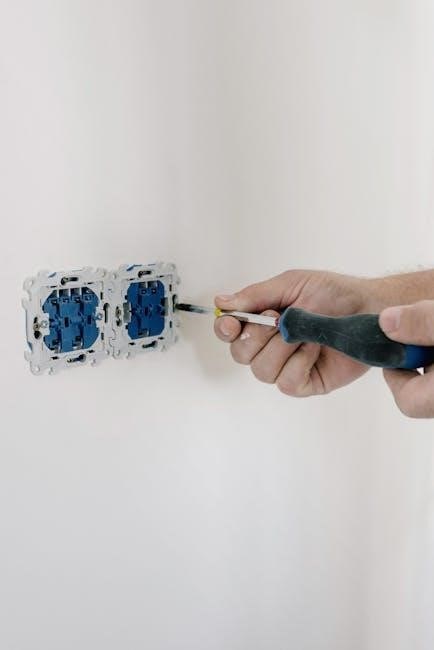
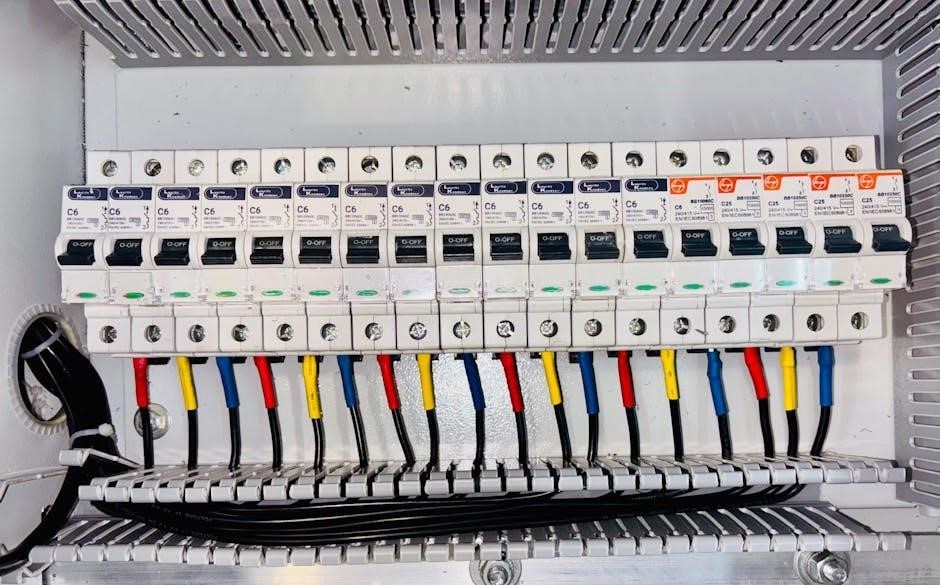
Before commencing wiring‚ always disconnect power to the circuit. Carefully route wiring‚ adhering to local electrical codes‚ ensuring sufficient slack for future servicing. Utilize appropriate gauge wiring for all connections‚ and clearly label each wire for easy identification.
Securely fasten the panel to the mounting surface using the provided hardware. Double-check all connections before restoring power‚ verifying polarity and tightness to prevent malfunctions and ensure optimal system performance.
Mounting the Impassa Control Panel
Selecting the ideal location is crucial for the Impassa control panel. Choose a central‚ indoor spot‚ shielded from direct sunlight‚ extreme temperatures‚ and potential water damage. Avoid areas near large metal objects that could interfere with wireless communication.
The mounting surface must be solid and capable of supporting the panel’s weight. Utilize the provided mounting template to accurately mark drill locations. Ensure the chosen height allows for easy access to the keypad and visual confirmation of system status.
Securely attach the panel using the supplied screws and anchors‚ verifying it’s level and firmly fixed. Proper mounting minimizes vibration and potential disconnections‚ contributing to long-term system reliability and performance.
Connecting the Power Supply & Backup Battery
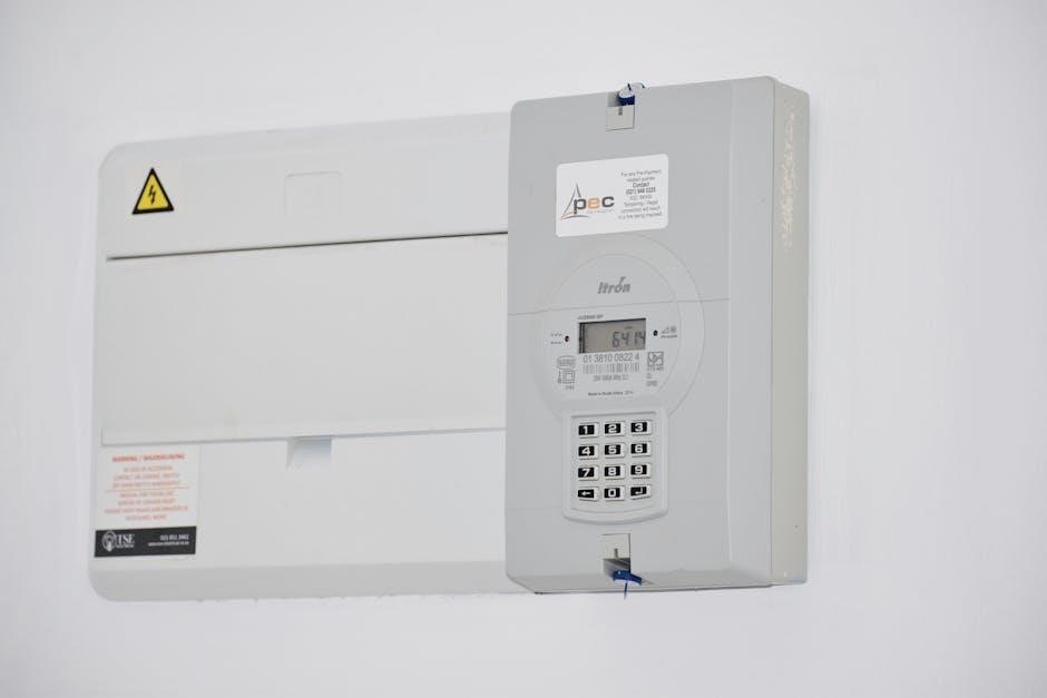
Prior to connecting power‚ ensure the Impassa panel is securely mounted. Connect the provided power adapter to a dedicated‚ grounded AC outlet. Verify the outlet’s voltage matches the adapter’s specifications to prevent damage.
Next‚ connect the power adapter cable to the designated power input terminal on the control panel. Simultaneously‚ install the backup battery‚ observing correct polarity (+ and -). The battery provides uninterrupted operation during power outages‚ maintaining security.
Once both are connected‚ power on the system. Observe the panel’s indicator lights to confirm proper power reception and battery charging. A fully charged battery is vital for system reliability‚ ensuring continuous protection even during extended power failures.
Zone Configuration & Wiring
Proper zone configuration is crucial for accurate alarm system performance. Each sensor connected to the Impassa panel represents a zone‚ categorized by its function – entry‚ interior‚ or perimeter. Accurate categorization ensures appropriate alarm responses.

Wiring zone inputs requires careful attention to polarity; Sensors utilize either normally open (NO) or normally closed (NC) contacts. NO contacts complete a circuit upon activation‚ while NC contacts break it. The Impassa panel must be programmed to recognize the correct contact type for each zone.
Incorrect wiring or programming can lead to false alarms or system failures. Always double-check wiring diagrams and zone definitions before powering on the system. Refer to the Impassa manual for specific wiring instructions and zone programming procedures.
Understanding Zone Types (Entry‚ Interior‚ etc.)
DSC Impassa utilizes diverse zone types to tailor security responses. Entry zones‚ typically doors and designated windows‚ allow a brief delay for disarming upon entry‚ preventing immediate alarms; Interior zones cover areas within the protected space‚ triggering instant alarms when breached while the system is armed.
Perimeter zones safeguard the building’s exterior – windows‚ doors‚ and potentially outdoor beams – offering early warning of potential intrusion. Instant zones activate the alarm immediately‚ regardless of arming status‚ ideal for critical areas like panic buttons.
Correctly identifying each zone’s purpose is vital for effective security. Misclassifying a zone can lead to nuisance alarms or compromised protection. The Impassa system allows customization of zone properties‚ enabling fine-tuning of security protocols to match specific needs.
Wiring Zone Inputs (Normally Open vs. Normally Closed)
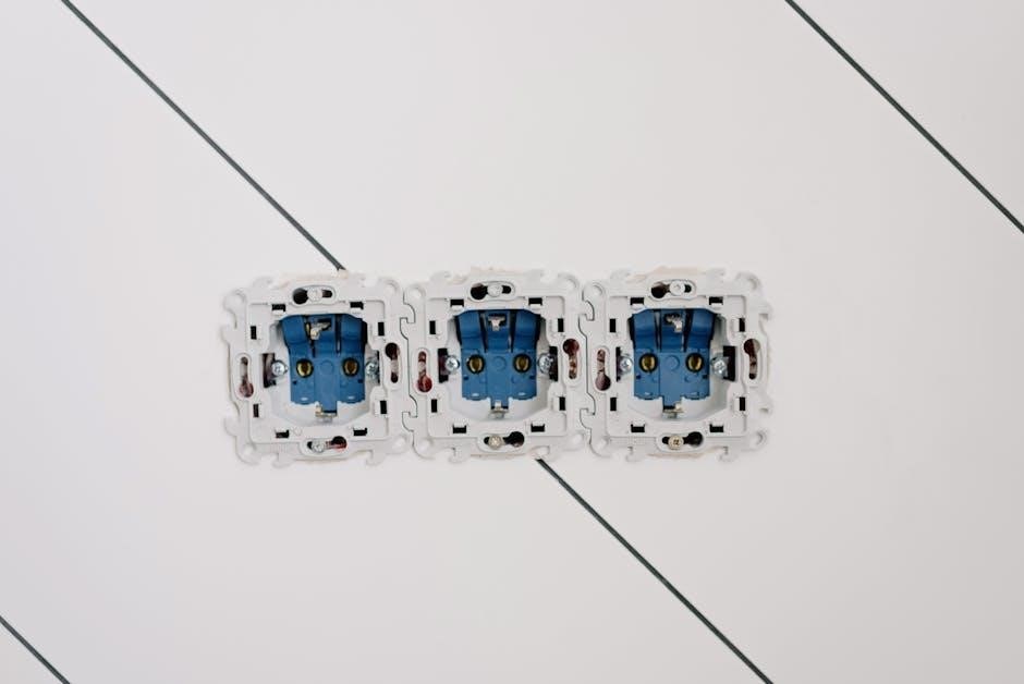
DSC Impassa zone inputs support both Normally Open (NO) and Normally Closed (NC) sensor configurations. Understanding this distinction is crucial for proper system functionality. Normally Open circuits are open (no connection) in their resting state; a break in the circuit (like a door opening) triggers an alarm. These require end-of-line resistors.
Normally Closed circuits are closed (connection present) at rest; a circuit break (wire cut) or short (tamper) triggers the alarm. NC sensors are often used for supervised circuits‚ offering tamper protection. The Impassa panel must be programmed to recognize the sensor type.
Incorrect wiring or programming can cause false alarms or system failures. Always verify sensor type and wiring polarity before connecting to the control panel. Proper end-of-line resistor values are essential for reliable zone supervision.
Keypad Installation & Programming
Keypads provide a crucial user interface for the DSC Impassa system‚ enabling arming‚ disarming‚ and system status monitoring. Installation involves mounting the keypad in a convenient‚ accessible location‚ considering both aesthetics and security. Wiring typically requires a four-wire connection to the control panel – power‚ ground‚ data‚ and auxiliary.
Programming involves assigning a unique ID to each keypad and configuring user access levels. Master codes grant full system control‚ while individual user codes offer limited access. Adjusting keypad volume‚ backlighting‚ and display settings enhances usability.
Proper programming ensures authorized access and prevents unauthorized system manipulation. Regularly review and update user codes to maintain security. Refer to the Impassa programming manual for detailed instructions and advanced configuration options.
Keypad Mounting Locations & Considerations
Strategic keypad placement is vital for both convenience and security. Ideal locations include near frequently used entry/exit doors‚ offering immediate access for arming and disarming the system. Avoid areas with high moisture or direct sunlight‚ which can damage the keypad.

Consider visibility – the keypad should be easily seen but not readily accessible to intruders. Mounting height should be comfortable for all users‚ typically between 48 and 60 inches from the floor. Ensure sufficient wiring access during installation.

Avoid mounting keypads behind obstructions or in areas prone to accidental damage. Prioritize locations that allow for quick and efficient system control during emergencies. Secure mounting hardware is essential to prevent tampering or removal.
Keypad Programming – User Codes & Access Levels

Establishing secure user codes is paramount for system integrity. The Impassa system allows for multiple user codes‚ each with customizable access levels. A “Master” code provides full system control‚ including programming and user management. Assign unique four-digit codes to each authorized user‚ avoiding easily guessable numbers like birthdays.
Different access levels can restrict user functions – for example‚ limiting some users to arming/disarming only. Regularly review and update user codes‚ especially after personnel changes. Utilize the keypad’s programming menu to add‚ delete‚ or modify user access.
Remember to document all user codes and their corresponding access levels for future reference. Consider enabling duress code functionality for discreetly signaling an emergency. Protect the Master code diligently to prevent unauthorized system alterations.
Wireless Device Pairing & Enrollment
Seamlessly integrating wireless devices expands your Impassa system’s capabilities. Begin by entering the panel’s programming mode‚ navigating to the wireless enrollment section. Each wireless sensor – doors‚ windows‚ motion detectors – possesses a unique identification number. Initiate the enrollment process on the keypad‚ prompting the sensor to transmit its ID.
The panel will confirm successful enrollment‚ assigning a zone number to the device. Repeat this process for each sensor‚ carefully documenting the assigned zone numbers. Prior to permanent mounting‚ conduct signal strength testing to ensure reliable communication. Weak signals may necessitate repositioning the sensor or utilizing a wireless repeater.
Verify proper functionality after enrollment by triggering each sensor and observing the corresponding zone activity on the keypad. Consistent signal strength is crucial for dependable security;
Adding Wireless Sensors (Doors‚ Windows‚ Motion Detectors)
Expanding your Impassa system with wireless sensors is straightforward. First‚ access the programming mode via the keypad‚ selecting the ‘Wireless Device Enrollment’ option. Each sensor requires individual enrollment; remove the battery tab to activate transmission. The panel will prompt for the sensor’s serial number‚ typically found on the device itself or its packaging.
Enter the serial number accurately‚ and the panel will assign a zone to the sensor – doors‚ windows‚ and motion detectors each require distinct zones. Confirm the zone assignment and sensor type during programming. Proper labeling of each zone within the system is vital for future troubleshooting and system management.
Repeat this process for each wireless sensor‚ ensuring each is uniquely identified and correctly assigned within the Impassa system.
Signal Strength Testing & Optimization
Reliable wireless communication is crucial for your Impassa system’s effectiveness. After enrolling wireless sensors‚ perform a signal strength test for each device. Access the ‘Wireless Signal Test’ function through the keypad programming menu. The panel will display a signal strength indicator‚ typically represented by a numerical value or a bar graph.
Weak signals can lead to false alarms or communication failures. If a sensor exhibits a weak signal‚ consider relocating it closer to the control panel or adding a wireless repeater to extend the range. Avoid obstructions like metal objects or thick walls that can interfere with the signal.
Optimizing sensor placement and utilizing repeaters ensures consistent and dependable wireless communication throughout your protected premises.
System Testing & Troubleshooting
Thorough testing is essential to confirm your Impassa system functions correctly. Initiate a ‘Walk Test’ through the keypad programming. This activates each zone sequentially‚ allowing you to verify the panel recognizes sensor activity. Observe the keypad display to confirm each zone triggers as expected during the walk test procedure.
Common installation errors include incorrect zone programming‚ wiring faults‚ and low battery levels in wireless devices. If a zone fails to trigger‚ double-check the wiring connections and sensor placement. Ensure all wireless sensors are properly enrolled and have sufficient battery power.
Refer to the troubleshooting section of this guide or the DSC website for solutions to specific error codes or issues encountered during testing.
Walk Test Procedure & Verification
To initiate a Walk Test‚ enter programming mode via the keypad. Navigate to the testing section within the programming menu – consult the full programming manual for specific key sequences. Once activated‚ the system will prompt you to test each zone individually.
Begin with Zone 1‚ then proceed sequentially through all programmed zones. For each zone‚ activate the sensor (open a door/window‚ trigger a motion detector). The keypad should display the zone number and a “Fault” or “Trip” indication.
Verify each zone is correctly identified and responds as expected. Any zones failing to register during the walk test require immediate investigation – check wiring‚ sensor functionality‚ and programming settings. Successful completion confirms basic system operation.
Common Installation Errors & Solutions
A frequent issue is reversed polarity during wiring‚ causing erratic sensor behavior. Always double-check wiring diagrams and ensure positive and negative terminals are correctly connected. Another common error involves incorrect zone programming – verify each zone’s type (entry‚ interior‚ etc;) matches its physical location and intended function.
Wireless signal interference can lead to dropped signals. Test signal strength at each sensor location and consider relocating the control panel or adding a signal repeater. Faulty sensors are also a common culprit; test each sensor independently to isolate the problem.
Finally‚ incorrect user codes or access levels can restrict system functionality. Review programming settings to ensure all users have appropriate permissions. Thorough troubleshooting and careful attention to detail are key to a successful installation.
Leave a Reply
You must be logged in to post a comment.